


A30 Auto Data Collection and Incline measurement
At the early days of 2013, Suzhou FOIF Co., Ltd announced the release of new generation GNSS Receiver-----A30
A30 is equipped with electronic bubble and tilt sensor, with these features you can get point position automatically without touch controller screen, it makes your job easily and quickly; and A30 can get corrected result although its supporting pole is tilt in 30°, surveyor don’t need to hold the supporting pole straightly always, with A30 enjoy job is possible.
Auto Data Collection
◆ Calibrate Electronic Bubble
To proceed auto measuring points, you need first adjust the electric bubble to make it corresponding with the mechanical bubble on the tribrach like followed picture:
 Fig.1
Fig.1
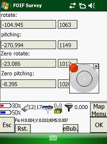 Fig.2
Fig.2  Fig.3
Fig.3
On Fig.1, after you level the mechanical bubble on tribrach where GPS receiver is set up, then go to the menu Instrument/Inclinometer Status. Click button “eBub” on Fig.2 to display electric bubble, then click button “Rst.” After this procedure has been done, electric bubble inside receiver will be fully corresponding with the mechanical bubble. Like Fig.3, electric bubble will go into center after calibration, click “OK” to confirm.
◆ Settings about Auto-Data Collection
Select “Survey/Measure points” to measurement menu, then switch to Fig.6, click “Opt.” button to do the settings. Like Fig.6, tick on “Tilt Survey”, then do the settings on eBubble sensitive.
 Fig.4
Fig.4 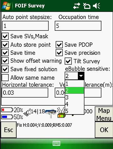 Fig.5
Fig.5
◆ Auto-Data Collection Operation
After settings, click “OK” back to measurement menu, like Fig.6 and Fig7, after centering the eBubble then current point measuring data would be collected and saved, no need to click measuring button.
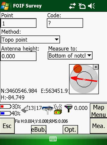 Fig.6
Fig.6  Fig.7
Fig.7
Incline measurement
Incline measurement means you can get corrected position although the pole is tilt 30°, measured result is same as measuring the points with the pole straightly.
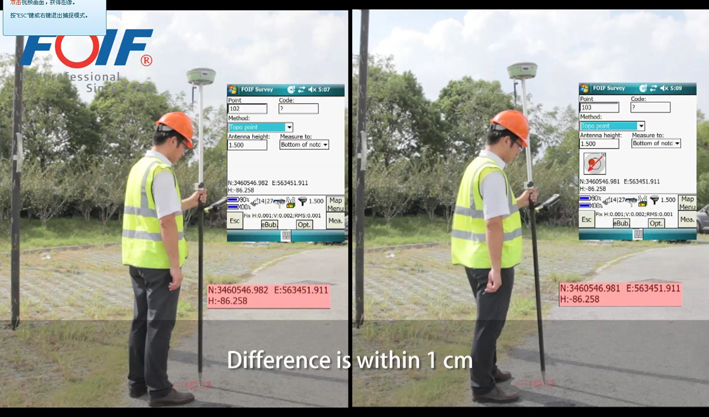 Fig.8
Fig.8
◆ Calibrate Electronic Bubble
Electric bubble adjusting job should be done in advance, select Instrument/Compass Status to calibration menu, click “Mark” button begin to calibrate, rotate GNSS receiver 720° smoothly, when finishing rotating, click “Stop” button to confirm
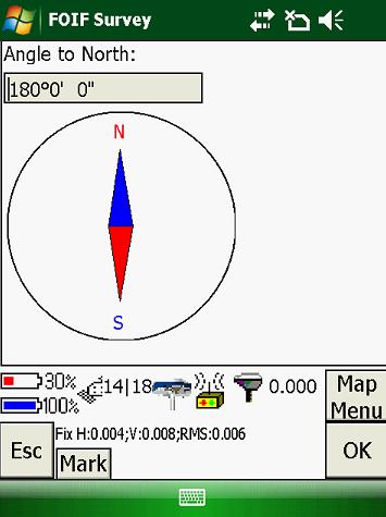 Fig.9
Fig.9  Fig.10
◆ Incline measurement
After all these settings are done, go to menu Survey/Incline Measure points, first input the antenna height at the column Fig.11, then you can start incline measuring points job, corrected result will be get although the pole is tilt, also correcting values will be shown following “Incline”, if correcting value is red, it means the tilting angle for GPS receiver is out of range, results should be invalid and not be saved to memory.
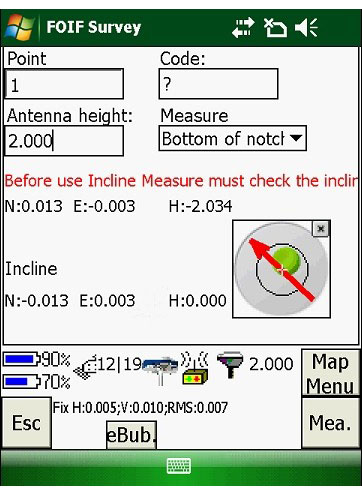 Fig.11